How would you size the truss elements of a bridge?
Learning Objectives
After completing this lesson, the student will be able to apply vector analysis to estimate forces on a structural member in a truss.
Next Generation Science Standards
- NGSS HS-ETS1-2
- CCSS.Math.Practice.MP1
- CCSS.Math.Practice.MP4
Units Used
- Mass: kilogram (kg)
- Length: meter (m)
- Time: second (s)
- Force: Newton (N) (1 N=1 kg m/s2)
Using Vectors to Find Forces on Truss Members
In the lesson on Trusses, we built a truss structure out of balsa wood members pinned together into triangular structures. Then, in the lesson on Truss Analysis we found that the reaction forces R1 and R2 are each equal to half the applied weight W.
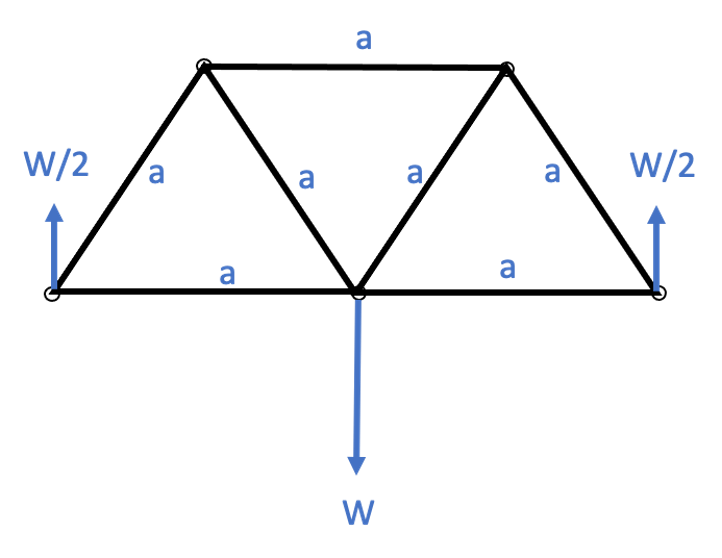
What if we needed to know the forces in each of those balsa wood members? Perhaps we want to figure out if we’ve opted for thick enough sections of wood to handle the weight we plan to apply, for example. They key to figuring out these loads are to use vectors! Recall, vectors have both magnitude and direction; and forces are a vector quantity. The weight applied is a vector acting downwards. The reaction forces are vectors acting upwards. The balsa wood members are helping carry the load – that means there are forces on those members in either tension, pulling on the member, or compression, pushing it together, which can be written as vectors aligned with the members. For example, if I want to solve for the forces in the members on the left-hand side, I can cut an imaginary slice in the truss, shown on the free body diagram below in red, to expose those forces.

Now my diagram looks like this:

I can solve for the forces by writing Newton’s law, that the sum of the forces is zero (the bridge still hasn’t flown away), and by accounting for the vertical direction and horizontal direction separately (the bridge isn’t flying away vertically, nor is it flying away horizontally). In the vertical direction, I only have two forces on my diagram, W/2 and F1. W/2 is entirely vertical, and F1 is at a 60 degree angle (recall this is an equilateral triangle). From trigonometry, we can then find the vertical component of F1 as F1sin(60). Summing forces in the vertical direction to find an equilibrium equation gives us:
W/2+F1sin(60)=0
Which means:
F1=-(W/2)(1/sin(60))=-W/√3
Wait, so there’s a minus sign there? That means that instead of pulling on that member, which mean it is in tension, the structure is pushing on that member, so it is in compression! We can now look at all the forces in the horizontal direction to find F2. Looking back at our figure, the only forces in the horizontal direction are F1 and F2. Our equilibrium equation in this horizontal direction is:
F1cos(60)+F2=0
Since we’ve already solved for F1 in terms of W, we can solve for F2 now as:
F2=-F1cos(60)=-(-W/√3)(1/2)=W/(2√3)
This is a positive value, so that horizontal member is in tension! Cool, right, so now I know that if I add 5 Newtons of weight, W, to my bridge at its midpoint, then those two members need to be strong enough to be able to carry:
F1= _____N
F2= _____N
With these skills in vectors, geometry, and trigonometry, you can extend this to analyze the complicated trusses you see all around you.
Next Steps
Have you gotten to break your truss yet? If not, get out your safety glasses and navigate to the lesson on Gusset Plates.
Or, move on to the unit on Balance to better understand weights and centers for your BLIMP.


Last updated: November 23, 2022.
