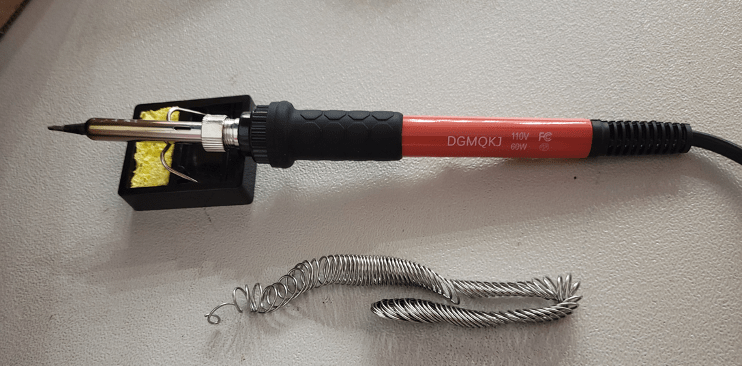
Prepare Soldering Station
This is the Jellyfish Propeller build (1 motor) that is compatible with the Tuna Flapping build (1 motors 1 servo) and the Tuna Propeller build (2 motors 1 servo).
If you have already made one of the blimps listed prior please skip to the motor assembly, if you have made a blimp prior and it is not listed above please skip to step 8. If not please continue to follow the guide below. For experienced makers you can skip to the wiring diagram to make the correct system with motors and servos.
- Turn on a fan or open windows if possible
- Wet the sponge that goes with the soldering iron – it is to remove excess solder from the iron
- Set soldering station temperature to 320 degrees Celsius
- Set-up stand so that the soldering iron can rest on it
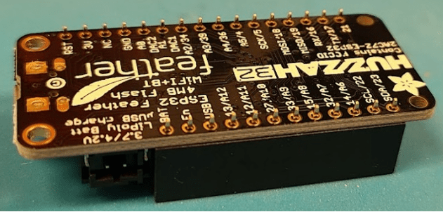
Attaching Pins to the “Feather Huzzah” Referred to as “The Board”
- Retrieve “Feather Huzzah” and “Feather header kit” from the Kit

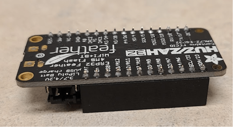
- Insert female Header Pins into Feather Board and rest the board on them – everything should sit flat and square when it is positioned as below. If everything is square, you are ready to solder each of the pins to the board.
- To solder the pins to the board one at a time:
- Touch the soldering iron to the header board pins and pin hole at the same time.
- Note: Do not breath the fumes.
- Touch the solder wire to the pin and the board.
- Remove soldering iron and solder wire once the melted material looks like a cone around the pins
- If there is excess material on tip of soldering iron, use the wet sponge to clean the tip before starting on the next pin and working your way down both sides of the board until all pins have been soldered.
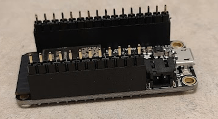
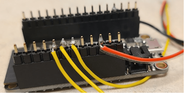
- Flip the board over and insert male Header Pins (longer side of the pins) into the top of the female Header Pins. If you have already made a previous system please take out the male Header Pins and replace them with a fresh set of male Header Pins to start making your new system.
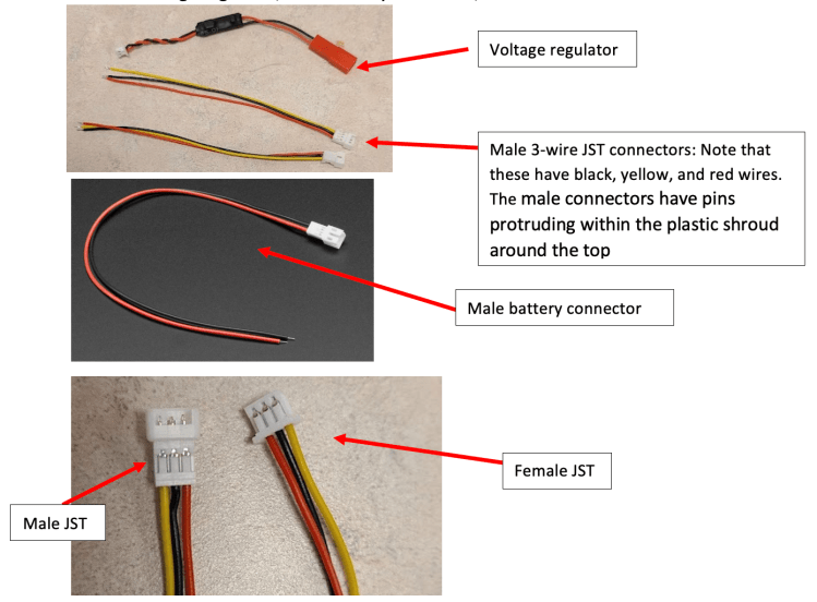
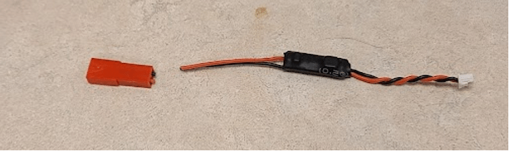
Preparing the Voltage Regulator Assembly
- Retrieve Voltage Regulator, male battery connector, and 1 male JST Connectors
- Use wire strippers (you can cut at the part that there are no dents for stripping off the plastic covering) to cut off red end of Voltage Regulator
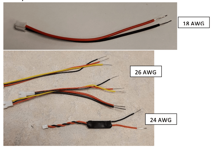
- Use wire stripper (the dent marked for appropriate AWG) to remove about 1 centimeter of plastic from the free ends of the voltage regulator, JST wires, and the battery connector
- Twist ends of exposed wires to prevent fraying
- Twist all 5 black wires together, and all 5 red wires together and use the yellow wire holder to hold them in place and then coat the wires with solder

- Bend wires to straighten and wrap black electrical tape around the exposed part of the wire. Tape red and black separately.

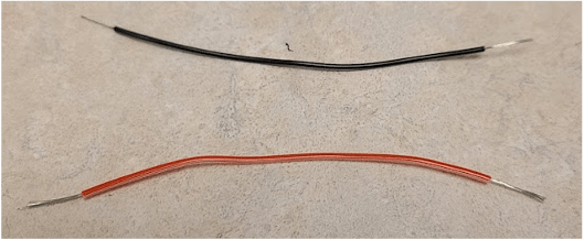
- Cut about 8 centimeters of rainbow-colored wire stack – note that there is a paper ruler in the kit if you need to measure.

- Remove a red and a black wire from the stack (note that they are not on the ends) and strip about 1 cm of material off each side of both wires
- Cut the white head off the twisted black and red wires on the voltage regulator

- Twist together the 2 black wires (piece of wire, voltage regulator, and JST) and coat with solder then repeat for the 2 red wires unbending and covering each junction with electrical tape when you are finished.

Wiring the “Feather Huzzah”
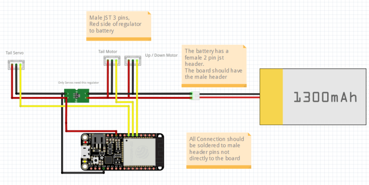
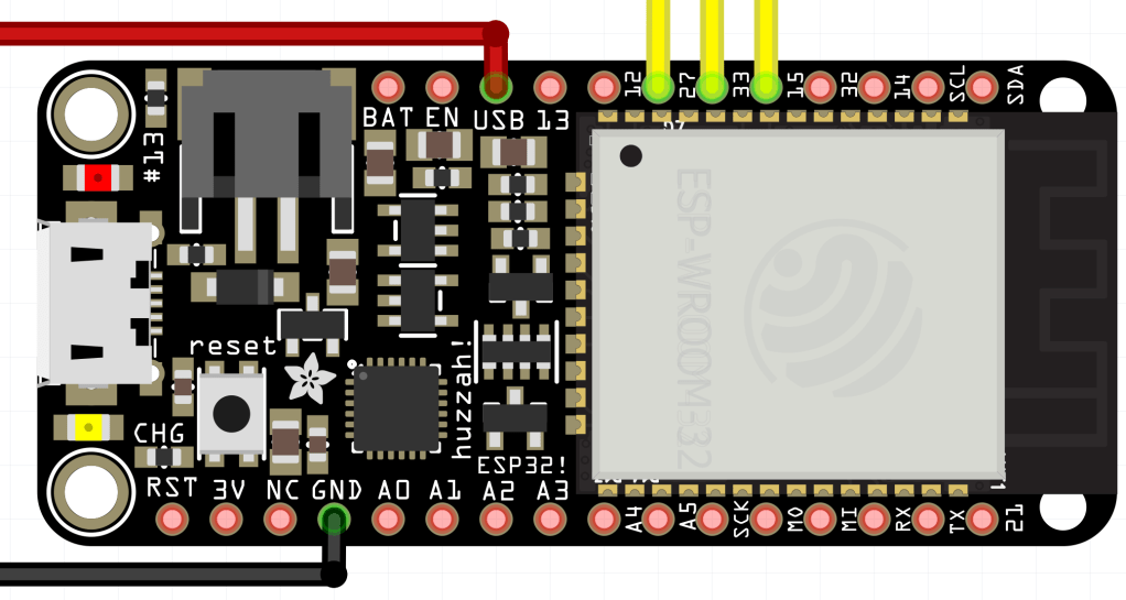
- Use the above diagram to identify which JST Connectors is for the motor.
- Now use the diagram to identify which pin each of the wires connects to.
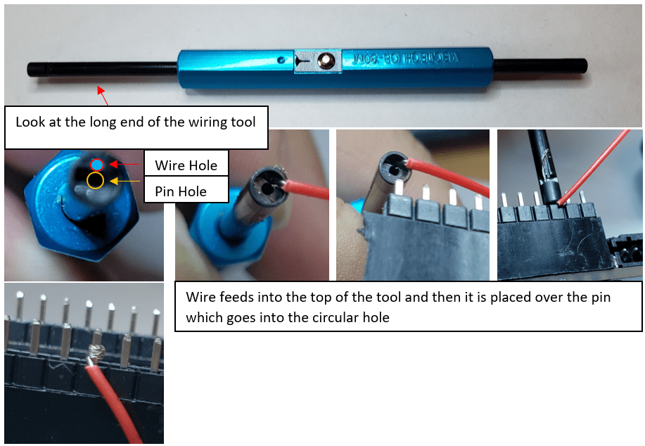
- Select one of the wires to start. Use the wire wrapping tool to twist the wire around the appropriate pin – insert the wire into the semi-circular hole at the top of the tool as far as it will go, bend the wire at a 90° angle so that it will stay inside the tool while the center hole is placed over the pin. Turn the tool so that the wire wraps around the pin. Repeat the wire wrapping for all of the wires in the diagram.
- Solder twisted wires on to the board being careful to not put on too much solder – the wires cannot touch other pins.
Preparing the Motors
- The Jellyfish uses 1 motors, so plug one Electronic Speed Controller (ESC) into the the male JST connectors that are soldered to your Feather Board at pin 15.

Battery Assembly
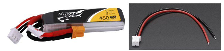
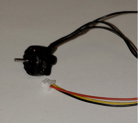
- Gather Battery Supplies – the battery and 2 pin female JST are needed. Note the white header with 3 wires connected to the battery is used for charging the battery.
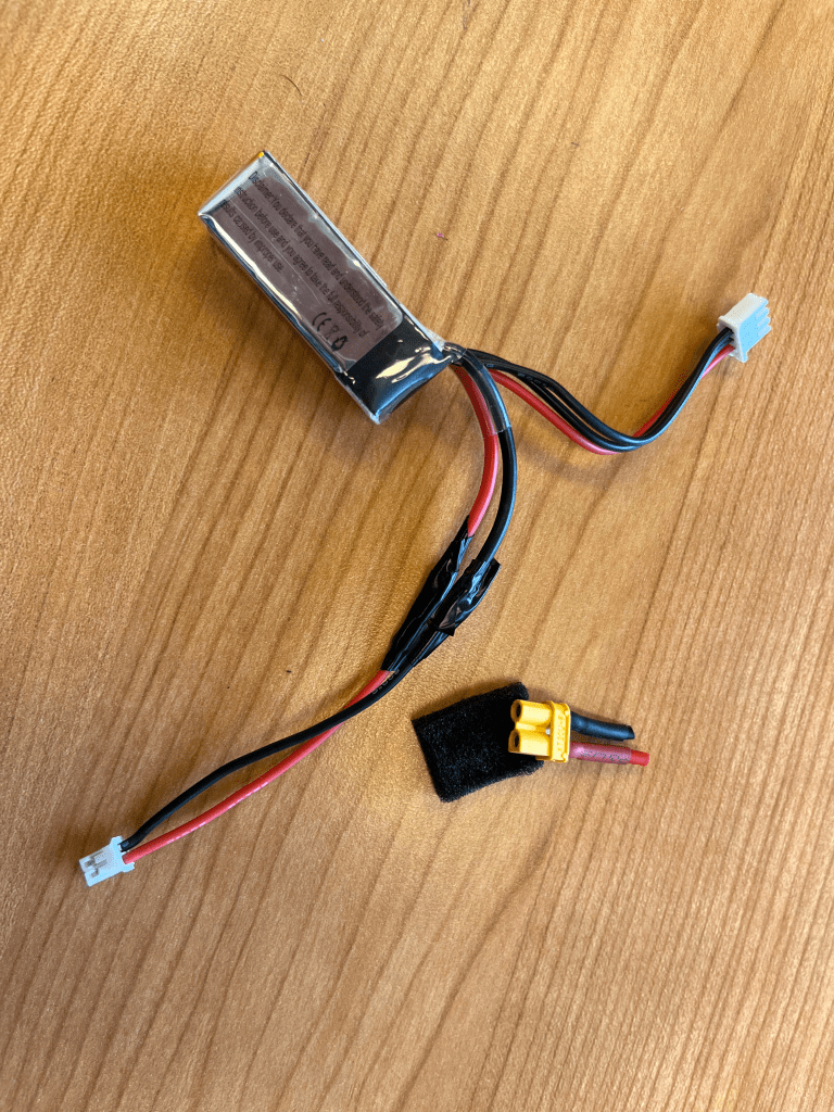
- ONLY cut the red cable connected to the yellow header then solder the red wire of the 2-pin female JST to it and apply electrical tape. Cutting both the red and black wires at the same time could inadvertently short the battery.
- Cut the black cable connected to the yellow header then solder the black wire of the 2-pin female JST to it and apply electrical tape.
Motor Assembly

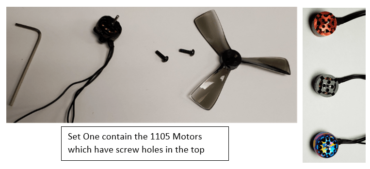
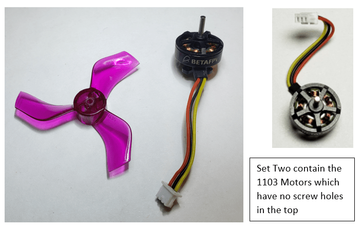
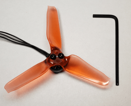
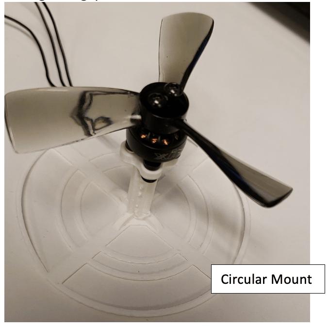
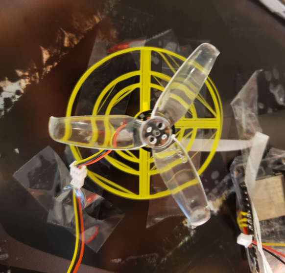
- For the Jellyfish you will need one motor. Connected to a circular mount. Pictured below is an example, motor and propeller. You may have different propeller shapes/colors in your kit. In set one you will need to screw down the propeller into the holes on top. For set two no screws are required.
- If your motors do not come with JST connectors pre-attached, you will need to attach female JST connectors to each of the motors. To do so, follow the same process as you have done previously by stripping the ends of the wires, twisting them, coating in solder, and wrapping with electrical tape.
- Screw in the Propellers – push the propeller onto the motor, line up propeller and motor holes, and then use hex screws to attach it.
- Screw the motor into the mount from below – you might need to clear plastic away from the screw holes on the mount before you begin. Use the hex screws included with the propellers. You will likely need to use the long end of the Allen wrench to reach the screws through the gaps in the mount.
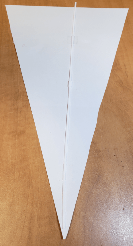
Fin Assembly
- Create fins to by using the 2 plastic sticks and a connector wish some construction paper. And fit the end of the stick into the plastic holder on the servo.
Jellyfish Construction
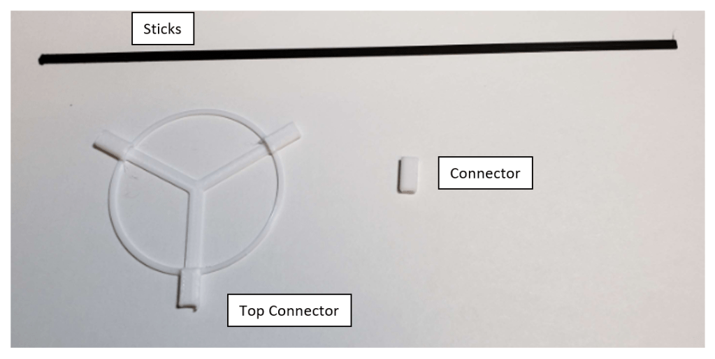
- Please grab all the Sticks, Top Connector, and Connectors. Then with a small amount of glue begin to assemble the outside struct by inserting the sticks into the holes of the connectors starting from the top connector. Do so by adding 4 sticks to the three sides of the top connector.
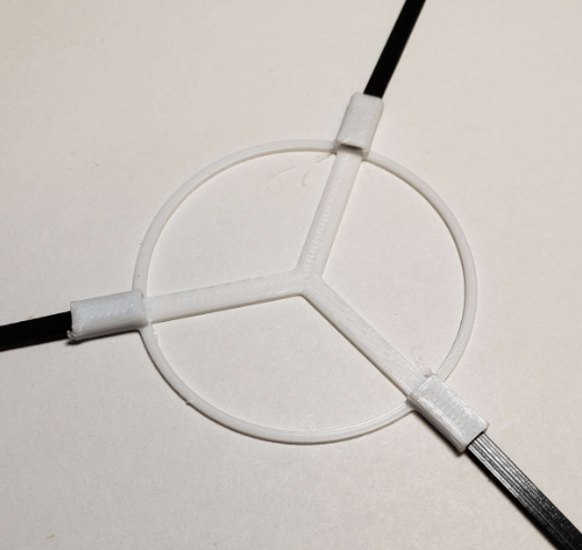
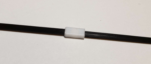
- Continue the linkage with connectors between sticks.
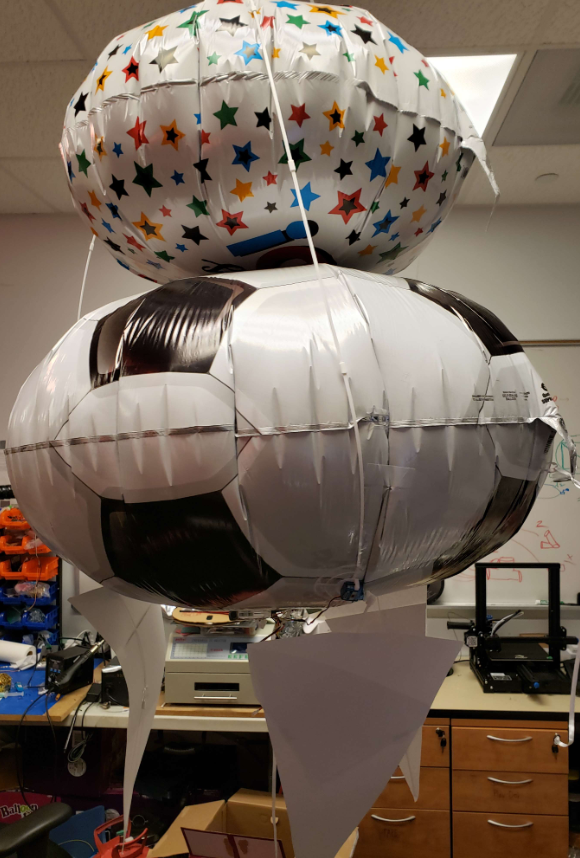
- With this structure completed inflate the two circular envelopes (one medium, one large) and connect them with the structure you’ve built. By placing the structure on top of the medium balloon and the medium balloon on the large balloon and using tape to hold down the structure and balloons.

Test the Electronics
- Tape motor mount to table to test electronics – you want the mount to be stable when the propeller turns on.
- Read over the software guide. You are now ready to upload code to the Feather and check for the MAC address of the controller. If there are others assembling the kit in the room they will all have the same MAC address so please refer to the Six Axis pair tool of the software guide.
- Attach the “Up/Down motor” to the ESC as labeled in the wiring diagram, pin 15.
- Attach battery to battery connector
- If you have not programed the feather, do not worry as it should be preprogrammed with the base code and should be able to connect the controller to the feather by turning on the controller and pressing start, this may take 10 – 30 seconds for the controller to pair to the feather.
- Using the right joystick of the controller up and down will move the motor on the circular mount, this will be used to move the blimp up and down.
Final Assembly
- Cover pointy pins on the board with electrical tape
- Follow the software instructions to prepare the controller and the board
- Fill the envelope with helium – make sure you secure the envelope with a string before adding helium so that it won’t float away (do not do this outside)
- Tape parts to envelope filled with helium
- Start by attaching the propeller attached to the servo to the bottom of the blimpMake sure the wires are taped down so that they are not in the way of the propeller.Attach the fins to the sides of the blimpAttach the feather and the battery between around the base of the blimp.Make sure all wires are taped down and secured and out of the way of the propellersTape playdough to the front of the envelope – add more playdough until it is “neutrally buoyant,” i.e., floats without rising or falling
- Note: if you wish to move the motors and servos, you can make extension wires with 3 wires from the rainbow-wire stack and a male and female JST soldered to opposing sides.
Jelly Fish Construction
- Add the Motor to the center along with the battery and electronics. Then mount the fins around the center aligned with the struct.
- Add the fins to where the structure ends on the balloon, and place the remaining electronics below the large balloon.
Last updated Nov 11, 2022.
