Learning Objectives
After completing this lesson, the student will be able to describe the functional flow and architecture of a system and integrate individual components to compose a system. The students will be able to identify test cases to charecterize system behavior and functionality.
Next Generation Science Standards
- NGSS HS-ETS1-3 “Evaluate a solution to a complex real-world problem based on prioritized criteria and trade-offs that account for a range of constraints, including cost, safety, reliability, and aesthetics, as well as possible social, cultural, and environmental impacts”
- -NGSS HS-ETS1-4 Engineering Design: “Use a computer simulation to model the impact of proposed solutions to a complex real-world problem with numerous criteria and constraints on interactions within and between systems relevant to the problem.”
- NGSS HS-ETS1-3 “Evaluate a solution to a complex real-world problem based on prioritized criteria and trade-offs that account for a range of constraints, including cost, safety, reliability, and aesthetics, as well as possible social, cultural, and environmental impacts”
- NGSS HS-ETS1-4 Engineering Design: “Use a computer simulation to model the impact of proposed solutions to a complex real-world problem with numerous criteria and constraints on interactions within and between systems relevant to the problem.”
Common Core State Standards
- CCSS.Math.Practice.MP1 “Make sense of problems and persevere in solving them”
- CCSS.Math.Practice.MP2 “Reason abstractly and quantitatively”
- CCSS.Math.Practice.MP4 “Model with mathematics”
- CCSS.Math.Practice.MP5 “Use appropriate tools strategically”
Supplies
- BLIMP Kit
- Computer to complete the exercises
Pre-Requisite
- Familiarity with BLIMP building instructions
Part A: What is a System?
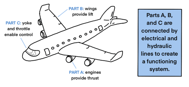
A system is composed of different elements that are designed to interact with one another to achieve a purpose that cannot be achieved by the elements alone. For example, a commercial aircraft is composed of many parts that are designed to work together to achieve its purpose of transporting goods and people. The body of the aircraft (called fuselage) is designed to provide the structure to hold the engine, wings, fuel tanks, cargo, landing gear etc. While each of these elements provide a specific function (e.g., engine provides thrust), all of these elements work together to safely move and fly the aircraft and its occupants.
Formally, “a system is an arrangement of parts or elements that together exhibit behavior or meaning that the individual constituents do not.” (INCOSE Fellows, 2019)
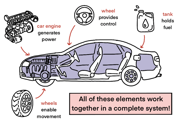
Let’s examine a few systems in the following figures:
A system has many attributes that help us understand and describe the working of a system. Let’s consider a commercial aircraft as an example of a system to discuss attributes a system. These attributes remain generally applicable to all systems that are engineered to achieve a purpose.
System Attributes:
Purpose: A system always has a purpose for which the different parts and components are brought together. A system must achieve its purpose to justify its existence. For example, the purpose of a commercial aircraft is to safely transport passengers and cargo via air.
Function: Function describes what does a system do to achieve its purpose. A commercial aircraft flies from origin to a destination to safely transport people and cargo. But to fly from origin to destination, the commercial aircraft has to “hold passengers and cargo”, “take-off from origin”, “maintain level flight”, “land at destination” to achieve its purpose.
Structure: Every system has a structure which describes what the system is like. Structure includes the shape and form of a system and identifies the different parts and components of a system. For our commercial aircraft example, the system has a fuselage, wings, control surfaces, engines etc.
Behavior: Behavior of a system describes how the different parts and components (i.e., structure/form) come together with system functions to achieve system’s purpose. For example, wings of the commercial aircraft provide lift while the engines provide the thrust to keep it moving through the air.
Hierarchy: A system can have many different parts and components and grouping them into sub-systems based on their function or structure can help describe their behavior. For example, the engine is one of the many parts of an aircraft, but the engine itself is composed of 100s of other parts such as fuel valves, air intake fans, control units etc. Hence, a system is composed of many sub-systems which in-turn may have their own sub-sub-systems. System hierarchy creates a decomposition of system into sub-system and further sub-systems into sub-sub-systems.
Operational Enviorment: A system performs its functions within an operational enviorment. This operational environment provides inputs to the system and may consume outputs from the system. For example, the operational enviorment of a commercial aircraft may include airports, flying in clam and turbulent weather etc.
System Boundary: The boundary of a system helps distinguish the operational environment of system from its own sub-systems. For example, the boundary of a commercial aircraft includes everything that is within the aircraft and all of its sub-systems but not the airport, runways, or the fuel stations which are part of an operational environment of the system.
Interface: The system interacts with its operational enviorment while its own parts and components interact internally. This interaction involves flow of matter, signals, data, and/or energy that are needed to accomplish system functions. Interfaces enable this flow of matter, signals, and energy. Internal interfaces connect the different sub-systems, parts, and components of a systems, while the external interfaces facilitate flow to and from the operational enviorment.
What system attributes can you identify in the following figure?

Part A Exercises:
- Describe 3 different functions of the BLIMP.
- Develop a system hierarchy of the BLIMP. Identify 3 sub-systems and two parts/components per sub-system. How did you decide on sub-system?
- Identify the internal interfaces between the sub-systems listed in problem 2 above. What flow these interfaces enable (energy, matter, data, or signals)? Why is this flow important?
- Identify an external interface for BLIMP? What flow this interface enables (energy, matter, data, or signals)? Why is this flow important?
Part B: Functional Flow and System Architecture
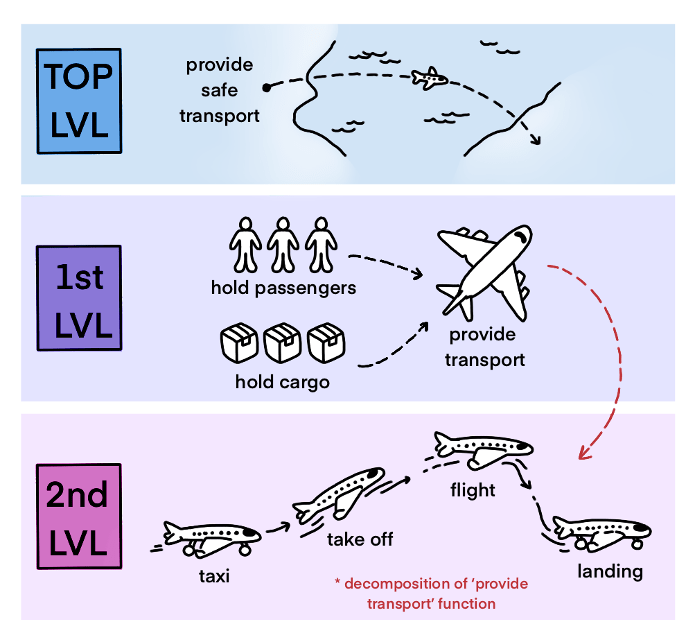
A function is a task or activity performed to obtain a certain outcome. A system performs one or more functions to achieve its purpose. A system has a top-level function which maps to the system purpose and this top-level function is decomposed into several sub-level functions. For example, a commercial aircraft top-level function is to provide safe transportation. This function can be decomposed into multiple sub-functions of “Hold Passengers”, “Hold Cargo”, and “Provide Transportation” etc. These functions can be further decomposed into sub-sub-level functions. For example, in order to provide transportation, the commercial aircraft needs to taxi, take-off, fly, and land. The activity of identifying the system functions and decomposing functions into sub-level functions is called functional decomposition of a system.
A function receives an input (signal, data, energy and/or matter) and transforms the input into an output (signal, data, energy, and/or matter). For example, in order to take-off, the commercial aircraft will need to determine the total weight of the aircraft. This means that “Provide Transportation” needs an output from the “Hold Passengers” (i.e., data) and “Hold Cargo” functions.
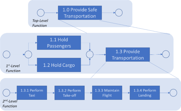
A “Functional Flow” diagram illustrates the decomposition and sequencing of functions that a system has to perform. Some functions need to be performed in parallel and some functions needs to be completed before another function can be performed (i.e., when there is an input/output dependency as discussed above). The following figure illustrates a simplified functional flow diagram of a commercial aircraft. Notice how each function is numbered to maintain top-level to 1st level and 2nd level dependency.
System Architecture and Integration: A system architecture describes what sub-systems, part, and/or components, perform which functions and what internal and external interfaces are needed. These interfaces establish the flow of signal, data, energy, and/or matter throughout the system. A system architecture integrates the structure (form) and function into one complete system.
A system architecture is obtained by allocating system functions to subsystems while ensuring there will be necessary flow of signals, data, energy, and matter to satisfy the input and output requirements of functions. For example, a system architecture may allocate the function “1.3.1 Perform Taxi” to aircraft landing gear (wheels and tires) and engines, while the function “1.3.3 Maintain Flight” could be allocated to engine, wings, and fuselage etc.
Side Note: In systems design and systems engineering, the architecture of a system plays a critical role and can take a long time to finalize. The architecture development evolves over many cycles, called iterations, because the structure of sub-systems requires knowledge of functions they will perform.
Part B Exercises:
- Identify the top-level, 1st level, and 2nd level functions of your BLIMP.
- Create a Functional Flow Diagram of your BLIMP.
- Identify which functions are allocated to what components in your BLIMP? (Note: system architecture in your BLIMP kit is carefully pre-designed and remains fixed.)
- Pick 1 internal and 1 external interface and identify the functions and sub-system involved in this interface.
Part C: System Performance Characterization and Evaluation
The architecture sets the foundations of system performance. Characterizing and evaluating system performance is a multi-faceted activity and is one of the primary jobs of system designers and system engineers.
System performance is directly tied to the system purpose and remains intertwined between systems functions and structure. Each system function can have an individually associated one or more measure of performance (MoP). These MoPs are affected not only by the sub-system which performs the function, but collectively by all other functions and the sub-systems, particularly on functions where there is an input-output dependency. In other words, the system architecture effects the MoP of all functions and hence the MoP of the entire system. Can you think of a few MoPs for a commercial aircraft?
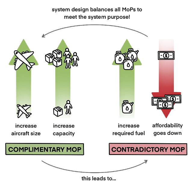
There are two major types of MoPs: complementary MoPs and contradictory MoPs. Complementary MoPs support one another, where increasing one also increases the other. Contradictory MoPs oppose one another where increasing one decreases the other. A system designer has to understand the inter-relationships across all MoPs to balance and optimize the overall system performance. This activity of analyzing system functions’ MoP based on their allocation to sub-systems in a system architecture is called Performance Characterization and Evaluation.
Consider, the top-level system function for commercial aircraft example to provide safe transportation. A MoP for this function can be the cost of transportation which one would prefer to minimize. Now consider the two sub-level functions “1.1 Hold Passengers” and “1.3 Provide Transportation” for instance. An intuitive MoP for these functions can be the number of passengers the aircraft can hold and how far the aircraft can fly to provide transportation, respectively. Ideally, one would like to increase both by carrying more weight and flying more distance, but these MoPs are contradictory given the top-level objective of minimizing the cost.
Part C Exercises:
- Identify 3 MoPs of functions in your BLIMP kit?
- Which pairs of these MoPs are complementary and which pairs are contradictory?
- Consider the sub-system these MoP come from based on the functional allocation (i.e., the system architecture). How are the MoPs affected by the sub-system?
Last updated August 15, 2022.
