Learning Objectives
After completing this lesson, the student will be able to calculate centroids and moments of inertia for different cross sections including thin-walled structures.
Next Generation Science Standards
- NGSS HS-ETS1-2 “Design a solution to a complex real-world problem by breaking it down into smaller, more manageable problems that can be solved through engineering”
Common Core State Standards
- CCSS.Math.Practice.MP1 “Make sense of problems and persevere in solving them”
- CCSS.Math.Practice.MP4 “Model with mathematics”
Supplies
- Ruler
- Balsa wood sheets
- Pins
- Wood glue
- Knife (see teacher or parent)
- BLIMP hulls
- Helium
Units Used
- Length: inch (in)
- Length: centimeter (cm)
- Length: meter (m)
Part A: Centroids
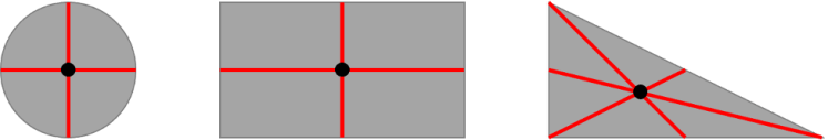
In geometry, the centroid is the mean position of all points in the shape – this point will be the center of mass if the shape is made of a uniform material. For example, a circle’s centroid is right in the middle of the circle. A rectangle’s centroid is where the line that connects the midpoints of the top and bottom intersects the line that connects the left and right sides. A triangle’s centroid can be similarly found by drawing lines connecting each vertex to the midpoint of the opposite sides.
An experimental way to find a centroid is to find the point where a shape balances on a pin’s point. You can try this with your balsa wood sheets – cut some arbitrary shape and balance it on your pin. You just found the centroid!
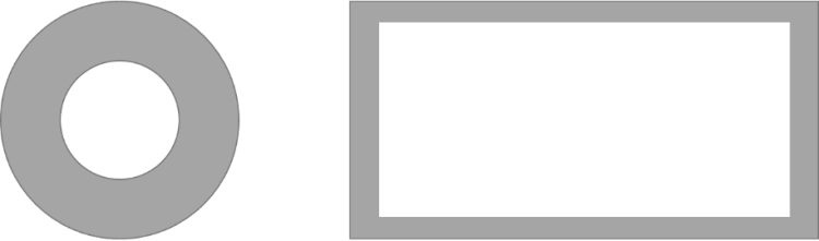
Sometimes the centroid of a shape is not actually on the shape. For example, consider a ring, where is the centroid? Mark the location of the centroid on the following figures:
Part B: Moments of Inertia
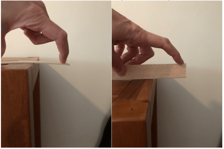
Let’s do an experiment. From your balsa wood sheets, cut a rectangle. I made mine 5 in (12.7 cm) long and 1 in (2.5 cm) wide. Hold it over the edge of a table with the wide side down, like a miniature diving board, and push on the end. Then rotate it 90 degrees so the narrow side is down. Push on the end. Which way bends more? Why?
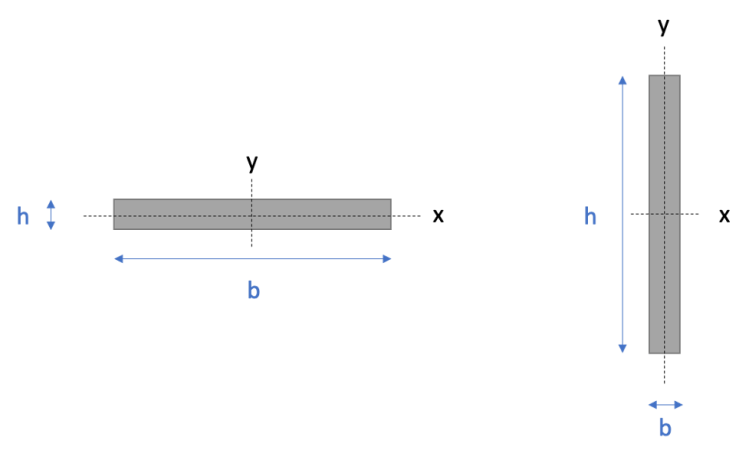
A structure’s moment of inertia (sometimes called the area moment of inertia or second moment of inertia), is a measure of how much a shape resists bending. For a rectangular cross section, the moment of inertia about its centroidal axis is written as 1/12 bh3, where b is the base of the cross section and h is the height of the cross section.
Calculate the moment of inertia for your balsa wood plank in these two orientations. Which one is larger? Which one resists bending better?
The real key here is that moment of inertia benefits from having as much area as possible as far as possible from the centroidal axis. If you have taken calculus, you can see this mathematically by calculating the moment of inertia as Ix=∫y2dA. An experimental way to see this is to build an I-beam. Cut two more balsawood planks matching the one you made previously, then glue the three planks together to make an I shape. Repeat your same experiment, hanging the beam off the side of a table and applying a force.
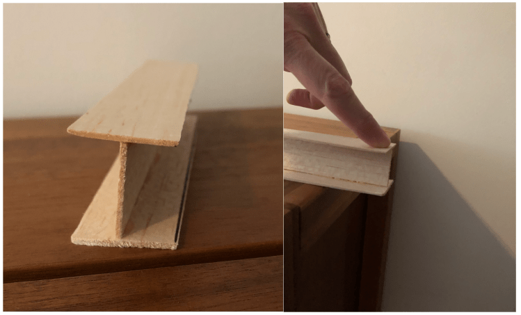
How did this I-beam fare in comparison to your prior experiments? Why do you think you had the result you did?
To dig into this more, a nice video tutorial is available at: https://www.youtube.com/watch?v=Bls5KnQOWkY.
Part C: Thin-Walled Structures
Get one of your BLIMP hulls. How strong is it? Can you bend it, twist it, etc? Of course you can. Now fill it with helium. It’s stronger now, right? Thin-walled structures, like your BLIMP appear in all sorts of engineering applications. Airplanes, submarines, fuel tanks – these are all thin-walled structures. One can do all sorts of clever things by combining thin-walled structures with other structural elements like beams and trusses. If you look deeper at an airframe, submarine hull, or fuel tank you will see that it is not solely its exterior shell that supports the structure, but a combination of structural members that all work together to make a structure that can resist bending, torsion, and all the loads that the structure is expected to carry. Check out the Goodyear Blimp’s “How It’s Made” website at https://www.goodyearblimp.com/behind-the-scenes/blimp-science.html, watch the video, and read through their descriptions of non-rigid, semi-rigid, and rigid airships.
Bonus: Biological Inspiration
We are drawing inspiration from biology with the three BLIMP hulls you have been provided. One of your hulls is shaped like a tuna fish, one like a ray, and one like a jellyfish. Think about how each of these fish move through water, and how much structural rigidity they need. Use what you have learned so far to devise a model for how you would represent each of these fish structurally.
Last updated May 23, 2022.
