Learning Objectives
After completing this lesson, the student will be able to use wing geometry to achieve desired stability, strength, and weight characteristics.
Next Generation Science Standards
- NGSS HS-ETS1-3 “Evaluate a solution to a complex real-world problem based on prioritized criteria and trade-offs that account for a range of constraints, including cost, safety, reliability, and aesthetics, as well as possible social, cultural, and environmental impacts”
Common Core State Standards
- CCSS.Math.Practice.MP1 “Make sense of problems and persevere in solving them”
- CCSS.Math.Practice.MP2 “Reason abstractly and quantitatively”
- CCSS.Math.Practice.MP4 “Model with mathematics”
Supplies
- Three BLIMP hulls
- Balsa wood components
- Pins
- Tape
- Helium
Units Used
- None – this is a math-free lesson!
Part A:
When an airfoil (or any body for that matter) moves through a fluid (air is a fluid), lift and drag are produced. The air is flowing faster over the top of the foil than the bottom, so there is lower pressure on top than on the bottom. This results in lift. Drag opposes the motion of the body through the fluid. Lift and drag are both vector quantities, so they have magnitudes and directions. Lift is the component of the aerodynamic force that acts perpendicular to the fluid flow and drag acts parallel to the fluid flow. On the airfoil below, sketch vectors for lift and drag.

These forces act at a location called the center of pressure. The center of pressure is to lift what center of gravity is to weight. The center of pressure though will change as we change the angle of the airfoil relative to the flow direction, known as the angle of attack. We can visualize the angle of attack as being the angle the airfoil makes with the airflow. To determine this angle, it is helpful to be able to visualize the chord for the airfoil. The chord is the line that connects the front (leading edge) and back (trailing edge) of the wing. Indicate on your drawing the chord for this airfoil and angle of attack of the airfoil relative to the flow direction.
Because the location of center of pressure changes with angle of attack, that’s a confusing location to use in analysis since it’s always changing. So, we often use instead the aerodynamic center, which is the point where the pitching moment due to these pressure forces (the moment causing the airfoil to rotate up or down) does not change with angle of attack. For most traditional low speed airfoils, the aerodynamic center is at about the quarter chord point – or 25% of the way from the leading edge to the trailing edge. Because this is a constant regardless of angle of attack, it is a much more convenient location to do analysis about!
Any shape moving through a fluid produces lift and drag, but some shapes are more efficient than others. Pull out your three BLIMP hulls and consider their shapes. Which do you think will move most efficiently through a fluid?
Let’s test out your hypothesis. Fill each hull with helium (be sure to tie a string to the hulls so you don’t have to retrieve them off the ceiling). Stand on one side of the room and give each balloon a gentle push. Which one goes the furthest? You may want to repeat this experiment a few times to make sure you are consistent with how hard your little push is. Was your hypothesis correct? Why or why not?
Part B: Wing Geometry
Consider the following four airplanes. What differences do you see between their wing configurations? Why do you think the differences occur?

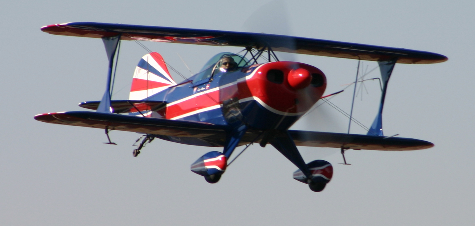


The first picture is a Piper Cub. This wing design is the simplest shown, for the most part having a constant chord. These types of wing structures are comparatively easy to build, making them desirable for low-speed, general aviation airplanes. The second picture is a Pitts aerobatic biplane. The two wings of a biplane allow for a smaller total distance across the wing – wing span. This lets the builder increase stiffness and reduce weight, but all those connecting structures along with the air flow interactions between the two wings results in more drag. The third plane is a Boeing 777. In that picture wing dihedral is particular visible. Dihedral is the upward angle of the wing.
When an airplane with wing dihedral starts to roll, the lower wing produces more lift, making the plane return to level flight. To visualize this, consider the sketch of an airplane below as though you are looking at it head on. Draw the lift vector on each wing. In which direction is the net moment on the aircraft due to the lift from each wing?

This natural roll-righting is a desirable trait for a passenger jet, but makes the plane less agile for a fighter jet, which is why you do not see it in the last picture of an F-14A.
A nifty trick that F-14 wings can do is change their wing sweep. A swept back wing has lower drag, and can fly at higher speeds without causing the flow over the wing to go supersonic. Why would the flow over the wing go supersonic? Think back to the airfoil we sketched in Part A. Recall we said that the flow is faster over the top of the foil than the bottom. This means the air is flowing faster over the top of the wing than the airplane is flying. So even if an airplane is flying below the speed of sound, the flow over the wing may go faster than the speed of sound! By sweeping the wing, we’ve reduced the component of flow travelling parallel to the wing chord, and can delay supersonic flow. A nice article with visual aids summarizing this is at: https://www.boldmethod.com/learn-to-fly/aerodynamics/wing-sweep/.
But, when you come in to land, it’s handy to have your wings not swept back. Those swept wings are made for speed, but will lose lift and stall at low speeds, so the F-14 was designed to do both – fly slow with the wings positioned forward, and fly fast with the wings swept back.

That’s some pretty cool engineering, right? And it’s biologically inspired! Have you ever watched an osprey go fishing? What do you see it doing with its wings when it dives? Morphing wings, like a wing that can change its sweep angle in flight, are a way we humans emulate nature with engineering innovation.
Part C: Structures and Aero/Hydrodynamics
Let’s combine what we’ve learned so far with structures and aerodynamics. Using your BLIMP structural kit components and your flying wing BLIMP hull, devise a way to turn your flying wing into a dihedral wing. Hint: using a gusset plate will let you provide support structures at multiple angles, and the tape will help secure the structure to the BLIMP hull. Be careful not to use pins anywhere near your inflatable hull. Experiment with how dihedral will cause the wing to self-correct if it starts to roll while moving forward. Alternatively, you can angle the wings downward, anhedral, to make the wing less stable but more maneuverable!
Bonus: Dive Deeper into Fluids
These three lessons were intended to give you a brief introduction to aerodynamics and hydrodynamics. For students interested in learning more, a great collection of lessons and activities is available on NASA Glenn Research Center’s website at: https://www.grc.nasa.gov/www/k-12/airplane/short.html.
Last updated June 1, 2022.
